

Make your own concrete spa
Want to build your own concrete hot tub but don't know where to start? This step-by-step guide walks you through the different stages involved in building the custom concrete spa shown above.
Whether you're researching concrete hot tub construction, a built-in concrete spa or a gunite spa project, this guide provides a practical overview of the main construction stages.
Please note that this guide is intended only as general assistance for building your spa. We strongly recommend consulting qualified professionals who can help you select the appropriate materials for your project.
Whether you're researching concrete hot tub construction, a built-in concrete spa or a gunite spa project, this guide provides a practical overview of the main construction stages.
Please note that this guide is intended only as general assistance for building your spa. We strongly recommend consulting qualified professionals who can help you select the appropriate materials for your project.
Concrete Hot Tub Specifications
- Dimensions: 240cm x 240cm
- Massage system: 6 hydrotherapy jets - 1 x 3 HP massage pump - 2 suction fittings
- Filtration system: 1 skimmer - 1 sand filter with 3-way valve - 1 x 0.33 HP filtration pump - 1 x 3kW heater
- Spa control system: BALBOA BP601 control box - TP800 topside control panel
- Lighting: SEAMAID sequential light with remote control
- Thermal insulation: Perimeter polystyrene insulation - 240 x 240cm Premium insulated hot tub cover
- Structural features: Perimeter bench seating - Concrete form block construction - Waterproof tanking coating
The construction work shown below was carried out by professional mason David Bureau from Innov'Maçonnerie.
This guide is intended only to outline the different construction stages used to build Mr. Robichon's concrete hot tub. We always recommend consulting a qualified professional when selecting materials and determining the appropriate masonry techniques for your installation. BOOSPA cannot be held responsible for any construction defects or improper workmanship.
This guide is intended only to outline the different construction stages used to build Mr. Robichon's concrete hot tub. We always recommend consulting a qualified professional when selecting materials and determining the appropriate masonry techniques for your installation. BOOSPA cannot be held responsible for any construction defects or improper workmanship.
How to Build a Concrete Hot Tub: Step-by-Step Guide

Step 1: Creating the Plan
This is probably the most important stage of the project and should never be overlooked.
The plan will accurately define the location of the different spa components and serve as a roadmap throughout the entire concrete hot tub construction project.
It will also determine the overall layout of the spa, including all the masonry elements that need to be built.
The plan will accurately define the location of the different spa components and serve as a roadmap throughout the entire concrete hot tub construction project.
It will also determine the overall layout of the spa, including all the masonry elements that need to be built.
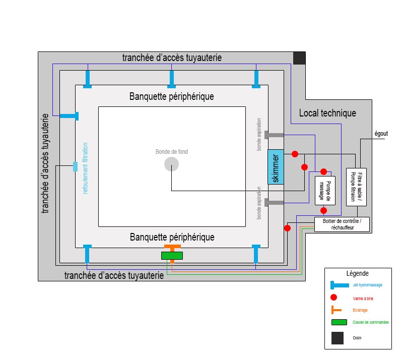
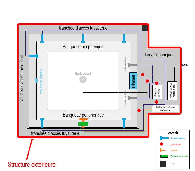
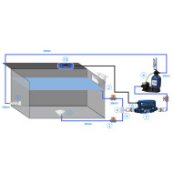
Here is the construction plan for the concrete hot tub featured in this guide.
Here are a few explanations regarding the placement of certain components:
- The ball valves have two functions:
- Closing the plumbing circuits so you can work on a spa component such as the pumps or sand filter without having to drain the hot tub
- Directing suction exclusively through the main drain when draining the spa to the sewer
- The filtration return is located on the opposite side from the skimmer to provide optimum water circulation
- The massage circuit uses two suction fittings to provide optimum massage performance. Since the hydrotherapy jets do not have Venturi air inlets, two suction lines are required to reduce flow restriction
- The plumbing access trench is important because it provides enough room to work on the pipes and identify any potential leaks
- A drain equipped with a sump pump must be installed to prevent rainwater from flooding the equipment area
Good to Know
Of course, this plan is only an example. You can modify it to suit your own concrete spa or hot tub project.
However, please follow these guidelines:
However, please follow these guidelines:
- If you want to install an air blower, the air jets must be located less than 1 meter from the waterline. Ideally, we recommend installing them in the bench seating.
- The hydrotherapy jet located farthest from the massage pump should be less than 5 meters away.
- If you want to control the spa equipment using pneumatic air buttons, these buttons must be located no more than 5 meters from the pump or blower they control.

Step 2: Excavation
Probably the least exciting part of the project. We recommend using a mini excavator. If you're feeling particularly ambitious, a pickaxe and shovel will be your best friends for many hours...
Make sure you excavate the entire footprint of the concrete hot tub, including the equipment area, which was excavated at a later stage on the spa shown in this guide. Doing everything at once means you'll only need the mini excavator once for the entire project.
Make sure you excavate the entire footprint of the concrete hot tub, including the equipment area, which was excavated at a later stage on the spa shown in this guide. Doing everything at once means you'll only need the mini excavator once for the entire project.
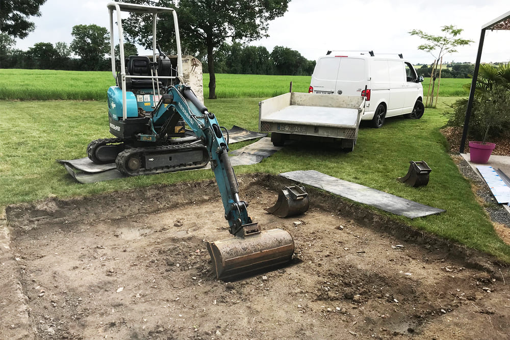

Make sure the excavation is perfectly level.
Good to Know
Allow an additional 20 to 30cm around the structure to make it easier to build the slab formwork and install the concrete blocks used for the hot tub structure.
As specified in the construction plan, installing a drain is essential.
It will help prevent the excavation from flooding during the masonry work.
Once the concrete hot tub is completed, it will also help prevent rainwater from flooding the different spa components.
It will help prevent the excavation from flooding during the masonry work.
Once the concrete hot tub is completed, it will also help prevent rainwater from flooding the different spa components.
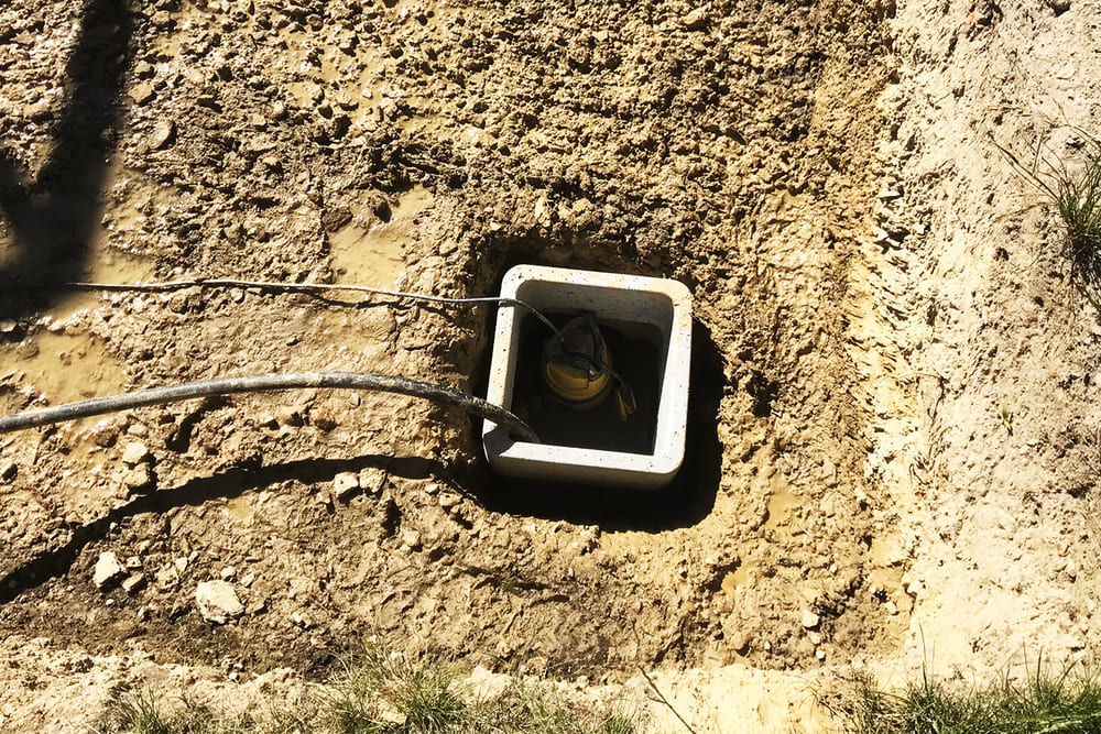
Drain pit equipped with a sump pump.

Step 3: Building the Concrete Slab
The slab is one of the most important structural components of the entire concrete hot tub project.
It will support the complete spa structure, the water inside the hot tub and the people using it.
In our case, the slab therefore needs to support more than 4 metric tons across an area of approximately 9m².
We therefore recommend a 20cm-thick fiber-reinforced concrete slab.
Building the slab involves several stages, which are explained below:
It will support the complete spa structure, the water inside the hot tub and the people using it.
In our case, the slab therefore needs to support more than 4 metric tons across an area of approximately 9m².
We therefore recommend a 20cm-thick fiber-reinforced concrete slab.
Good to Know
- The slab can also be reinforced using steel reinforcement, in which case fiber-reinforced concrete is not required.
- In both cases, we recommend using a concrete admixture to improve the waterproofing properties of the structure.
Building the slab involves several stages, which are explained below:
Step 3A: Build the Formwork
We won't go into detail about how to build the formwork for the concrete slab.
Simply make sure the form boards are securely held in place using reinforcing bars so they cannot move when the concrete is poured.
Fill the additional excavated area with gravel to provide optimum support.
Simply make sure the form boards are securely held in place using reinforcing bars so they cannot move when the concrete is poured.
Fill the additional excavated area with gravel to provide optimum support.
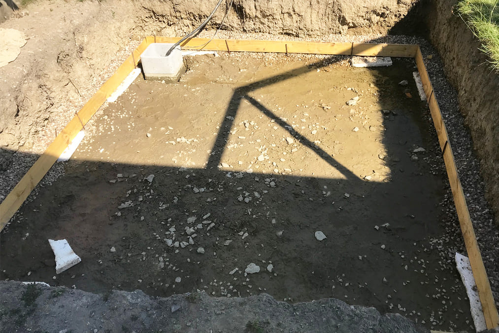
You can also see that an extension was installed to raise the drain.
Good to Know
One question you may have at this stage is: why not install steel mesh to reinforce the slab?
This is a valid question. A slab without steel mesh can provide sufficient structural strength for this concrete hot tub project provided that fiber-reinforced concrete is used and the ground is stable.
If you have any doubts about soil stability, you can reinforce the slab with steel reinforcement. Different types of reinforcement can be used, including reinforcement cages, welded wire mesh and reinforcing bars.
This is a valid question. A slab without steel mesh can provide sufficient structural strength for this concrete hot tub project provided that fiber-reinforced concrete is used and the ground is stable.
If you have any doubts about soil stability, you can reinforce the slab with steel reinforcement. Different types of reinforcement can be used, including reinforcement cages, welded wire mesh and reinforcing bars.
Step 3B: Install the Main Drain
Installing the main drain before pouring the concrete slab is essential. We recommend securing it in position using a small amount of fast-setting concrete.
If your slab uses steel reinforcement, make sure the main drain extends 4 to 5cm above the upper reinforcement mesh to allow for the thickness of the concrete and waterproof finish.
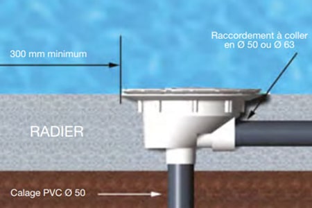
Unfortunately, we don't have a photo illustrating this stage.
Good to Know
The main drain must, of course, be connected to the filtration plumbing. Make sure the connection is completely watertight.
You won't be able to access this connection once the slab has been poured!
You won't be able to access this connection once the slab has been poured!
Step 3C: Pour the Main Concrete Slab
Mineral fiber-reinforced concrete was used to provide improved thermal insulation and help reduce heat loss.
Ask a professional mason for advice. They can recommend materials suitable for concrete hot tub construction.
This slab is a crucial part of the project. It provides the long-term stability and foundation of the entire structure.
Pay particular attention to the quality of the slab and allow the required curing time before moving on to the next stages.
Ask a professional mason for advice. They can recommend materials suitable for concrete hot tub construction.
This slab is a crucial part of the project. It provides the long-term stability and foundation of the entire structure.
Pay particular attention to the quality of the slab and allow the required curing time before moving on to the next stages.
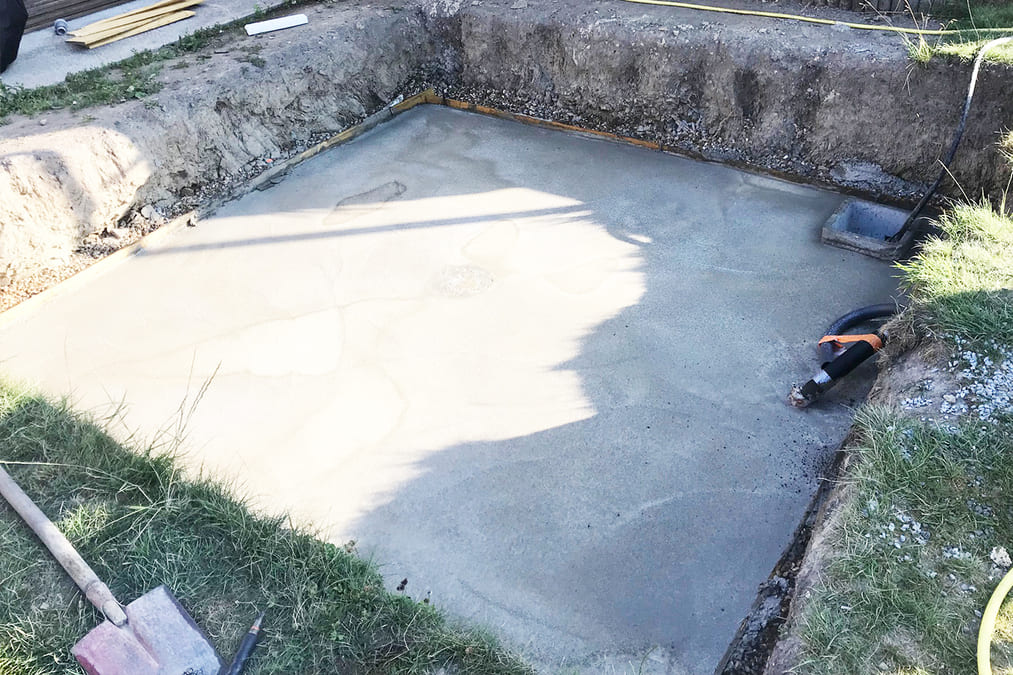
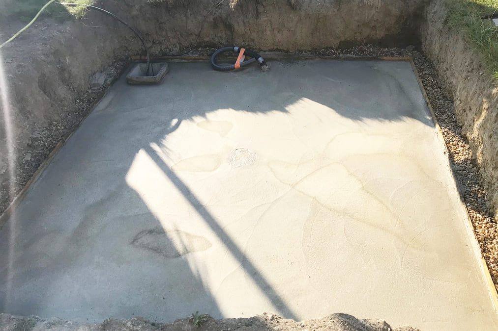
Make sure the slab is perfectly smooth and level, and remember to protect the main drain.
Good to Know
The pipes were installed inside protective sleeves to prevent damage to the plumbing embedded in the concrete.
Step 3D: Pour the Equipment Area Slab
A second slab was built for the spa equipment area.
As mentioned previously, this section was added later on the project shown here. We recommend building it directly at this stage.
As mentioned previously, this section was added later on the project shown here. We recommend building it directly at this stage.
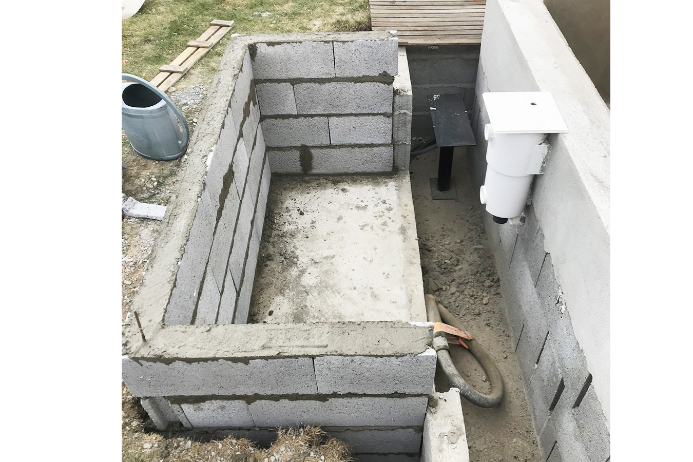
In our case, this section was built after completing the main structure.
Good to Know
You'll notice that the equipment area slab is raised by 30cm compared with the lower slab.
This elevation is important because it helps prevent pumps and electronic spa equipment from being flooded.
This elevation is important because it helps prevent pumps and electronic spa equipment from being flooded.
Step 3E: Mark Out the Structure
Accurately mark out the complete hot tub structure as well as the plumbing access trenches.
Accurate positioning is essential and should be carried out with maximum precision.
Always refer back to the construction plan created during the first stage.
Accurate positioning is essential and should be carried out with maximum precision.
Always refer back to the construction plan created during the first stage.
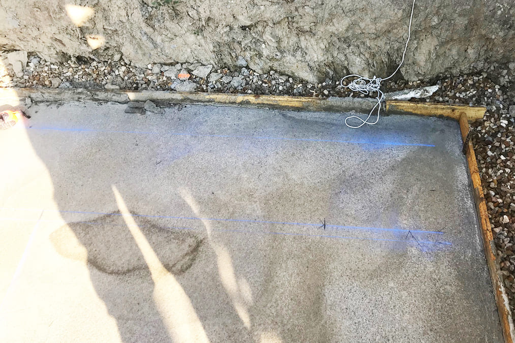
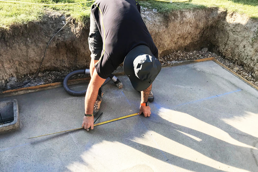
Don't hesitate to add plenty of reference marks for positioning the concrete form blocks.
Good to Know
Take into account the thickness of the waterproofing coating as well as the thickness of the tile if you want to mark the final finished dimensions on the concrete slab.
In the following photo, only the final interior dimensions of the lower section were marked in black.
In the following photo, only the final interior dimensions of the lower section were marked in black.
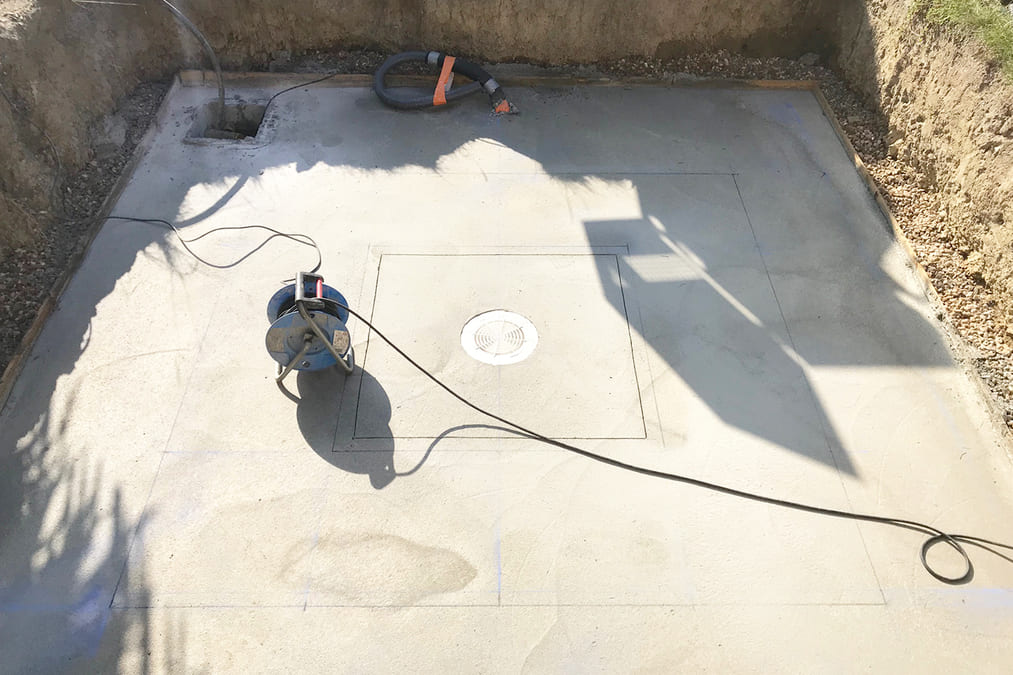
Final result after marking out the structure.

Step 4: Building the Concrete Hot Tub Structure
Once the slab is completely dry, it's time to start building the exterior structure of the concrete spa.
The structure is built in several stages, as explained below:
Good to Know
Allow the full 31-day slab curing period.
The concrete must be completely cured before carrying out any additional masonry work.
The concrete must be completely cured before carrying out any additional masonry work.
The structure is built in several stages, as explained below:
Step 4A: Build the Exterior Structure
We won't provide detailed instructions for building this structure.
Instead, here are a few photos showing the masonry work used for this particular concrete hot tub.
As mentioned previously, the equipment area was added later and is therefore not shown in these photos.
Instead, here are a few photos showing the masonry work used for this particular concrete hot tub.
As mentioned previously, the equipment area was added later and is therefore not shown in these photos.

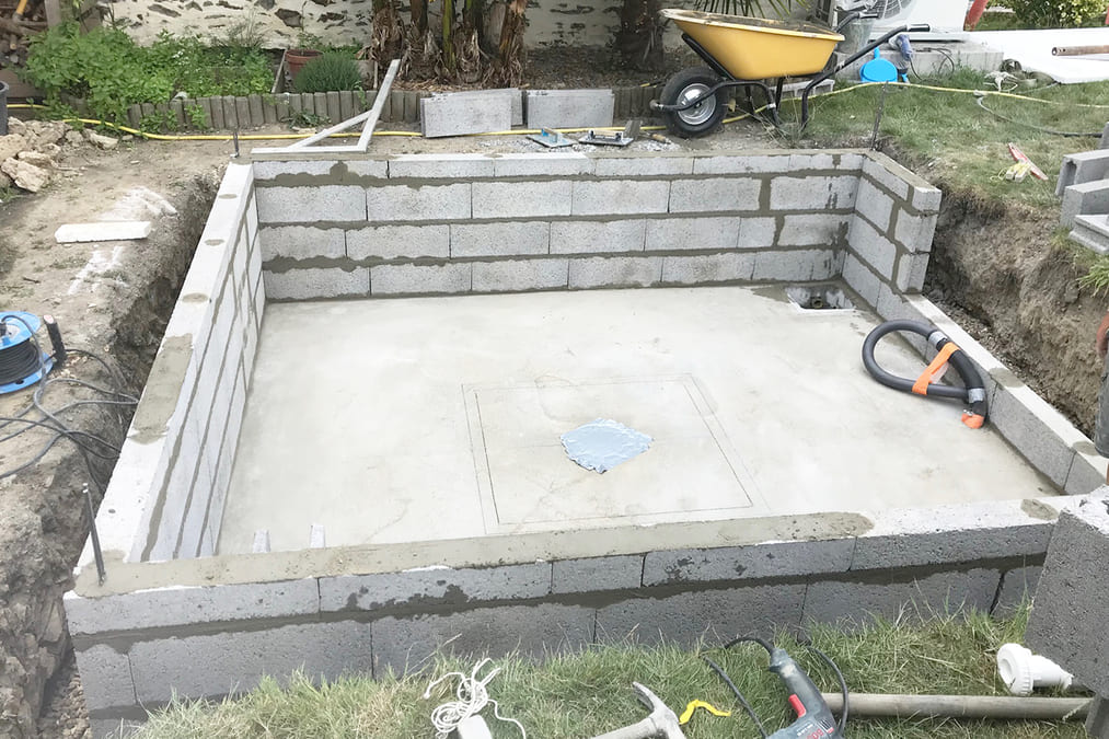
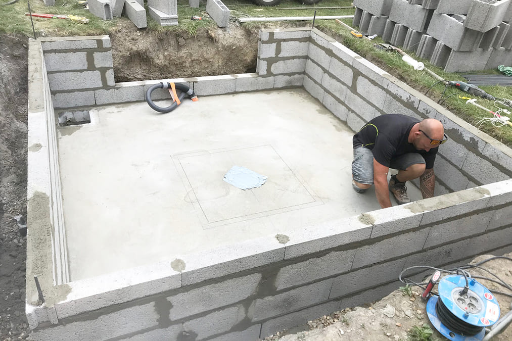
Steel reinforcement was installed at all four corners of the exterior structure. The slab was drilled to a depth of 10cm to secure the reinforcing bars.
Step 4B: Reinforce the Interior Structure
The interior structure must be able to retain 2.5 metric tons of water. It therefore needs to be built with great care.
Steel reinforcement is essential for the internal structure. Reinforcing bars are installed every 20cm and anchored directly into the slab to a depth of 10cm.
Steel reinforcement is essential for the internal structure. Reinforcing bars are installed every 20cm and anchored directly into the slab to a depth of 10cm.
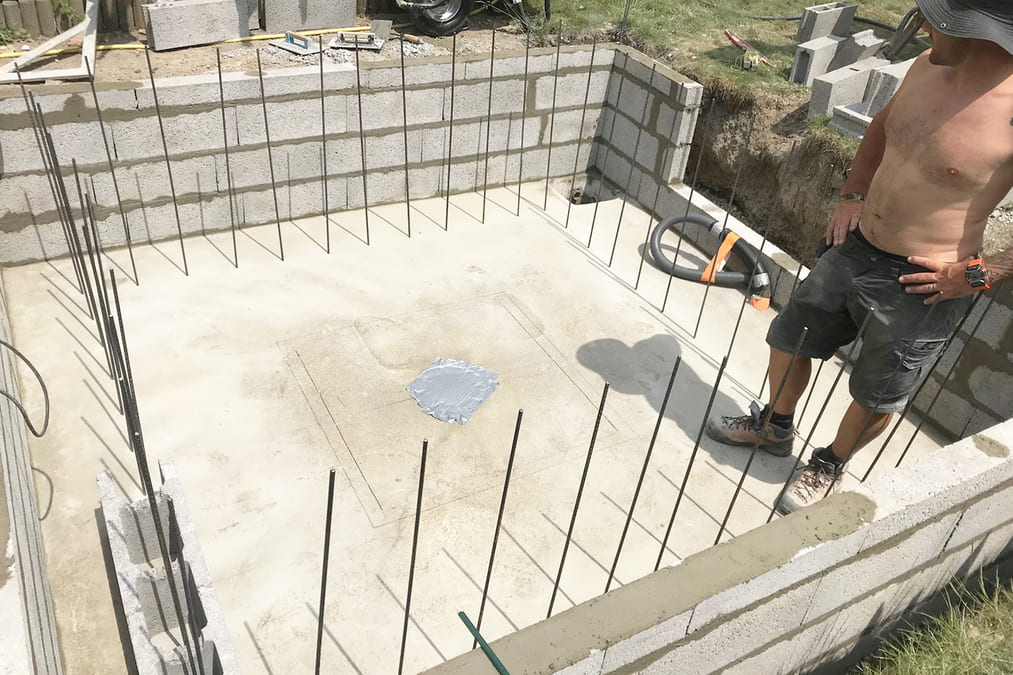

Horizontal perimeter reinforcement was also installed in every row of concrete form blocks.
Good to Know
The concrete form blocks were modified to accommodate the horizontal perimeter reinforcement.
Step 4C: Pre-Position the Concrete Blocks
The title says it all: pre-position the concrete form blocks and the built-in spa fittings, making the required cutouts.
Check the level regularly.
Check the level regularly.
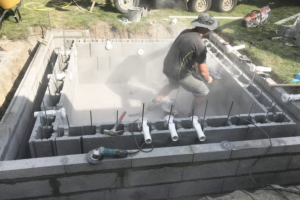

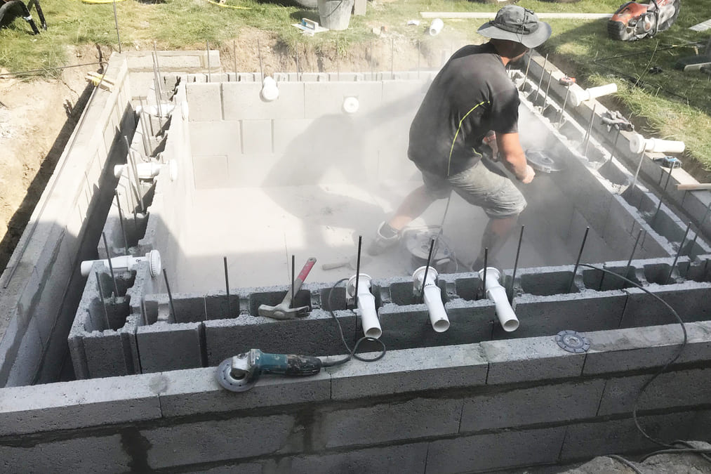
The cutouts should be made according to the construction plan. Please disregard the additional jets shown in the photos.
Step 4D: Pre-Set the Spa Components
This stage consists of positioning and securing the spa components inside the concrete form blocks.
Each component must be secured in place with concrete.
Several important details are shown in the following photo:
Each component must be secured in place with concrete.
Several important details are shown in the following photo:
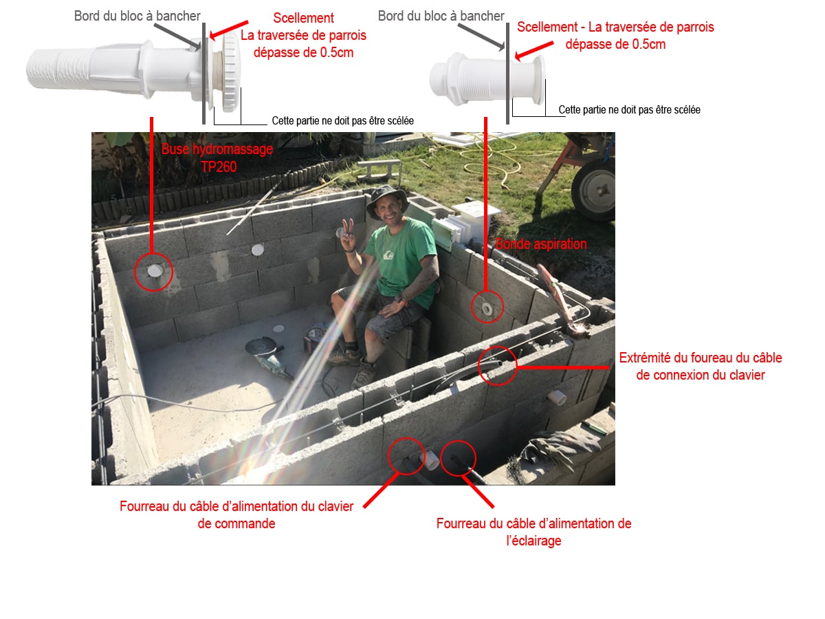
Position the components according to the specifications listed below.
- The wall fittings must extend by 1cm to allow for the thickness of the waterproofing and finishing material that will later be applied to the inside walls of the concrete hot tub
- DO NOT EMBED the threaded sections shown in the diagram in concrete under any circumstances
- The end of the topside control panel cable conduit must terminate inside the concrete form block. The other end must pass through the block and exit into the plumbing access trench
- Remember to connect the lighting cable conduit to the light wall fitting. This conduit must also exit on the plumbing trench side
- As with the jet wall fittings and suction fittings, allow the skimmer to extend by 1cm
Step 4E: Build the Lower Structure
As with the interior spa structure, install reinforcement in the lower structure.

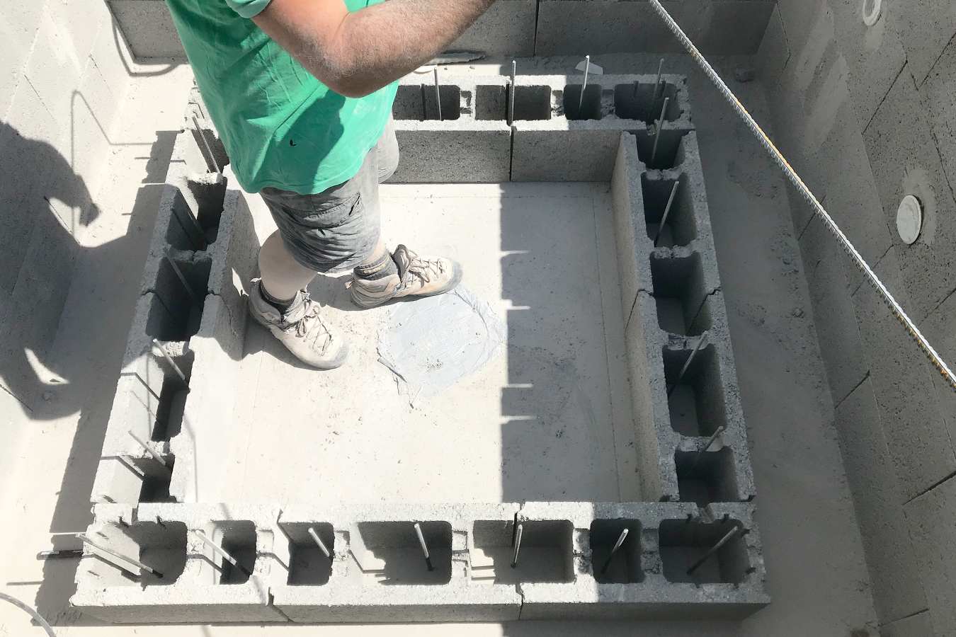

Vertical reinforcing bars plus horizontal perimeter reinforcement in every row of concrete form blocks.
Good to Know
The slab was drilled 10cm deep to secure the reinforcing bars. The spacing between the reinforcing bars is 20cm.
Step 4F: Fill the Concrete Form Blocks
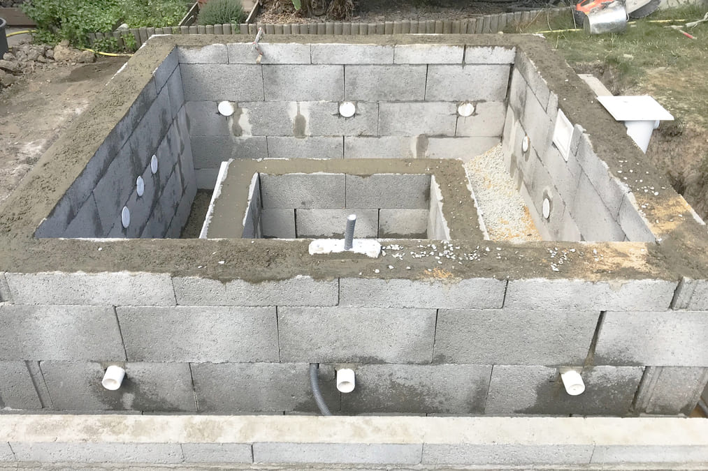
First, create the mold for the topside control panel using a polystyrene board.
This will create a recessed cavity for the control panel.
Fill the concrete form blocks with concrete.
Also fill the trench between the interior and lower sections of the spa with standard gravel up to 10cm below the upper edge of the bench.
The bench will also be insulated with a 6cm layer of polystyrene.
The remaining 4cm below the upper edge of the bench will be filled with concrete.
This will create a recessed cavity for the control panel.
Fill the concrete form blocks with concrete.
Also fill the trench between the interior and lower sections of the spa with standard gravel up to 10cm below the upper edge of the bench.
The bench will also be insulated with a 6cm layer of polystyrene.
The remaining 4cm below the upper edge of the bench will be filled with concrete.
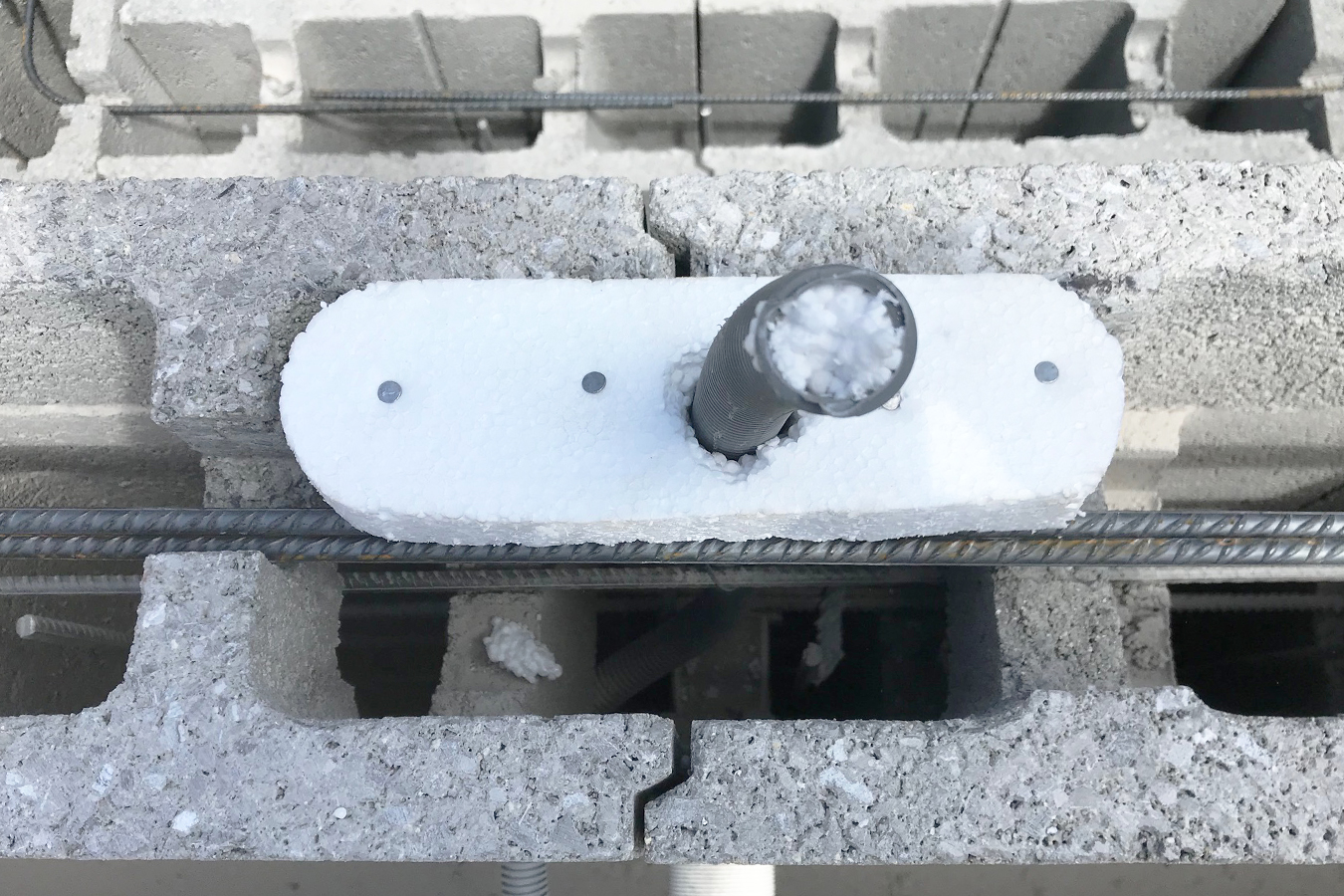
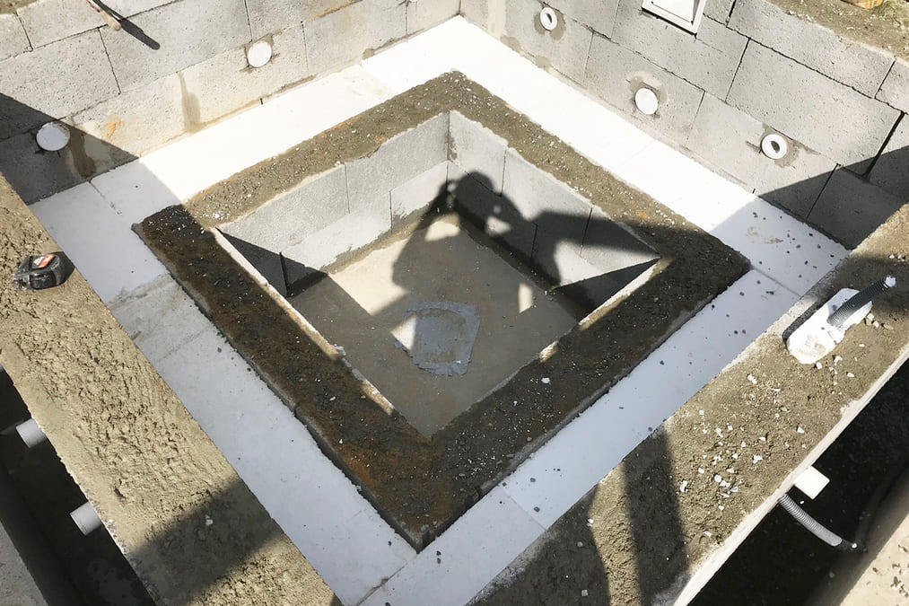
Cut the polystyrene insulation to achieve the result shown here.
Good to Know
The polystyrene insulation helps reduce heat loss and also significantly reduces the amount of concrete required to complete the bench.

Step 5: Waterproofing the Concrete Hot Tub
It's time to waterproof your concrete spa. If you filled it with water at this stage, your hot tub would look more like a giant strainer...
Step 5A: Apply the Waterproof Tanking Coating
We will waterproof the concrete hot tub shell using a waterproof tanking coating.
We recommend hiring a professional for this stage or, at minimum, obtaining professional advice when selecting the waterproofing product.
THIS IS NOT A STANDARD MASONRY COATING. This waterproofing layer is responsible for making the concrete spa shell completely watertight.
We recommend hiring a professional for this stage or, at minimum, obtaining professional advice when selecting the waterproofing product.
THIS IS NOT A STANDARD MASONRY COATING. This waterproofing layer is responsible for making the concrete spa shell completely watertight.
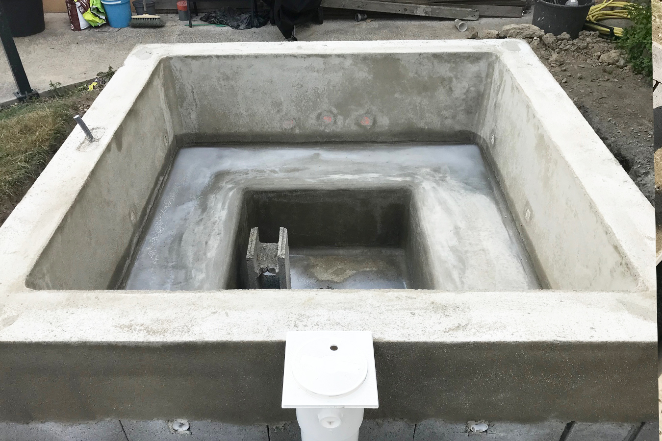
Application of the first waterproofing coat.
Several coats will need to be applied, particularly inside the hot tub shell. Once again, follow the recommendations provided by the professional or waterproofing product manufacturer.
The required drying time between coats must be strictly followed to achieve proper waterproofing.
The required drying time between coats must be strictly followed to achieve proper waterproofing.

Final result after all waterproofing coats have been applied.
Good to Know
Once the waterproof coating has been applied and is completely dry, we recommend working on the inside corners to bevel them before installing the tile.
It is better to avoid sharp edges inside the hot tub to reduce the risk of cuts.
It is better to avoid sharp edges inside the hot tub to reduce the risk of cuts.
Step 5B: Apply the Protective Layer
The waterproofing coating can deteriorate over time due to heat, water pH and the chemicals used to sanitize and maintain hot tub water.
It is therefore important to apply a protective layer over the waterproof coating.
You can skip this stage if you install tile or mosaic, as these will act as the protective layer.
In this project, even though tile was eventually installed, a double protection system was chosen: tile plus a protective coating.
Ask a specialist for advice on which protective product should be applied over your waterproofing system.
It is therefore important to apply a protective layer over the waterproof coating.
You can skip this stage if you install tile or mosaic, as these will act as the protective layer.
In this project, even though tile was eventually installed, a double protection system was chosen: tile plus a protective coating.
Ask a specialist for advice on which protective product should be applied over your waterproofing system.
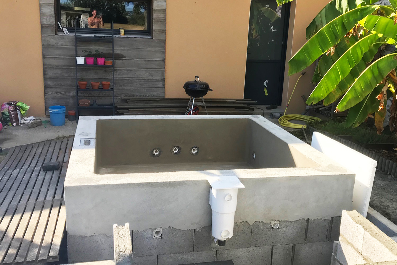
Final result after applying the protective layer inside the concrete spa shell.
Good to Know
The tile installation was postponed for one year. This is why a protective layer was applied inside the hot tub shell.
A high-temperature waterproof paint was then used.
Since the final result was not satisfactory, the paint had to be removed before tile was eventually installed.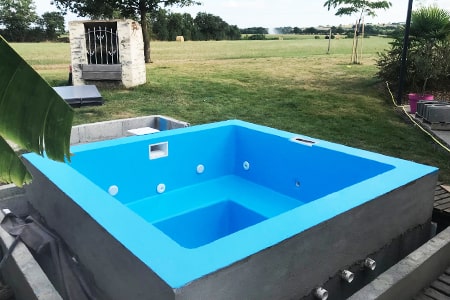
A high-temperature waterproof paint was then used.
Since the final result was not satisfactory, the paint had to be removed before tile was eventually installed.
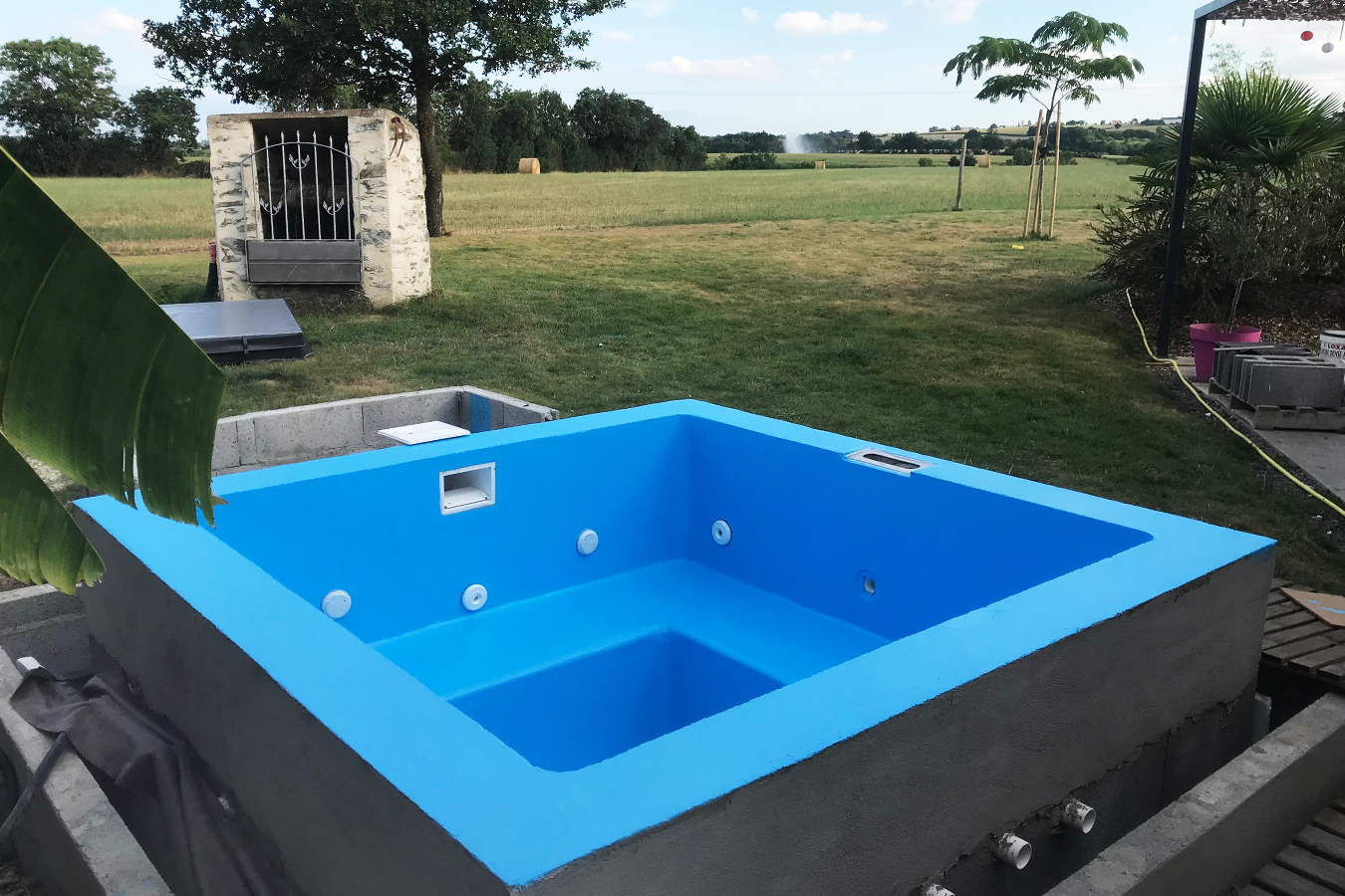
As a bonus, here is the result with blue waterproof paint.
Step 5C: Install the Topside Control Panel
Remove the polystyrene mold to expose the recess for the topside control panel.
Cut the conduit as required so the control panel can be recessed into the structure.
Adjust the opening until the control panel fits perfectly.
A stainless-steel plate was fabricated to provide a stable and complete support for the topside control panel.
You'll also notice that the masonry was shaped to create a sloped surface and prevent water from collecting around the control panel.
The support was screwed into place and sealed using silicone.
Cut the conduit as required so the control panel can be recessed into the structure.
Adjust the opening until the control panel fits perfectly.
A stainless-steel plate was fabricated to provide a stable and complete support for the topside control panel.
You'll also notice that the masonry was shaped to create a sloped surface and prevent water from collecting around the control panel.
The support was screwed into place and sealed using silicone.

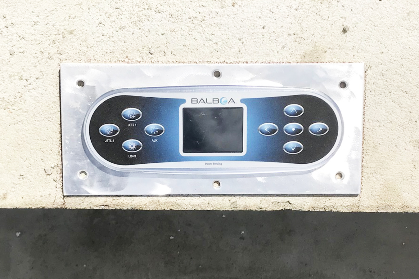

Carefully waterproof the support. The seal between the support and the control panel is provided by an M3 supplied with the control panel.

Step 6: Electrical Connections and Hot Tub Plumbing
Made it this far? Congratulations — you're entering the home stretch!
Step 6A: Main Electrical Supply
It's time to start installing the spa equipment. The electrical supply that powers all the components of your concrete hot tub now needs to be installed.
In this project, a circuit breaker was installed directly inside the equipment area.
This circuit breaker is connected to a main 32A circuit breaker located in the home's main electrical panel.
It is important to remember that the breaker in the main electrical panel is connected to a dedicated 40A residual-current device.
Once again, consult a qualified electrician.
Only a qualified professional can validate the electrical installation.
In this project, a circuit breaker was installed directly inside the equipment area.
This circuit breaker is connected to a main 32A circuit breaker located in the home's main electrical panel.
It is important to remember that the breaker in the main electrical panel is connected to a dedicated 40A residual-current device.
Once again, consult a qualified electrician.
Only a qualified professional can validate the electrical installation.
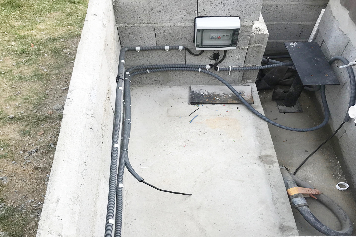
The electrical panel located in the equipment area also includes a 32A circuit breaker. This is not mandatory but was recommended so the power can be shut off without returning to the home's main electrical panel.
Good to Know
The residual-current device shuts off the electrical supply when leakage to ground is detected and therefore helps protect people.
The circuit breaker shuts off the electrical supply when a short circuit is detected and therefore helps protect the equipment.
The circuit breaker shuts off the electrical supply when a short circuit is detected and therefore helps protect the equipment.
Step 6B: Install the Pumps and Sand Filter
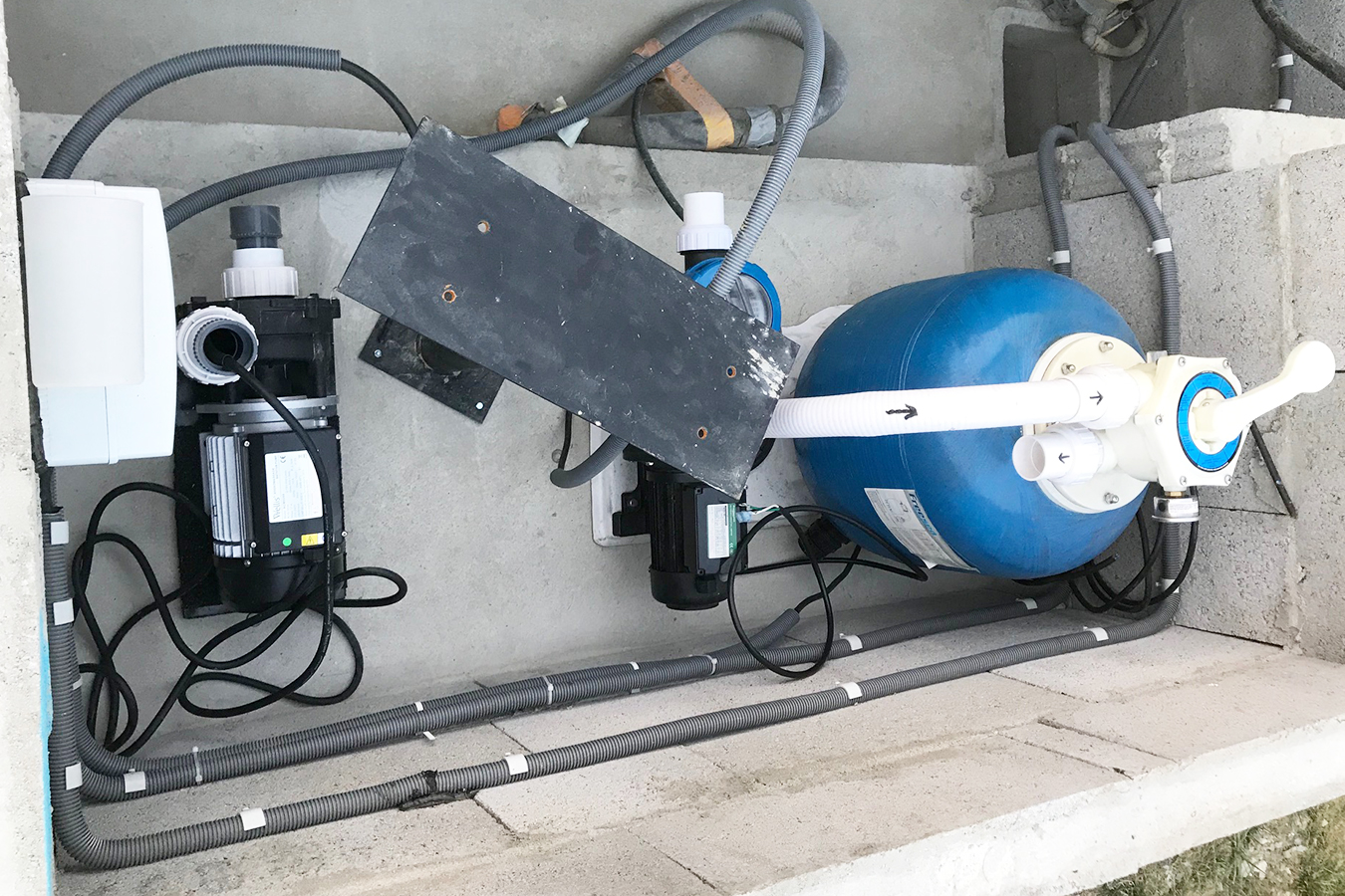
You can also install a rubber pad underneath the equipment to help reduce vibration.
You'll also notice the black metal support fabricated by Mr. Robichon.
This support will hold the spa control box. Raising this main component helps protect the equipment if the drainage pump fails.
This helps reduce the risk of electrical damage to other spa components caused by a general short circuit in the control box.
You'll also notice the black metal support fabricated by Mr. Robichon.
This support will hold the spa control box. Raising this main component helps protect the equipment if the drainage pump fails.
This helps reduce the risk of electrical damage to other spa components caused by a general short circuit in the control box.
Consider marking the direction of water flow on the fittings with a permanent marker.
Step 6C: Insulate the Concrete Hot Tub
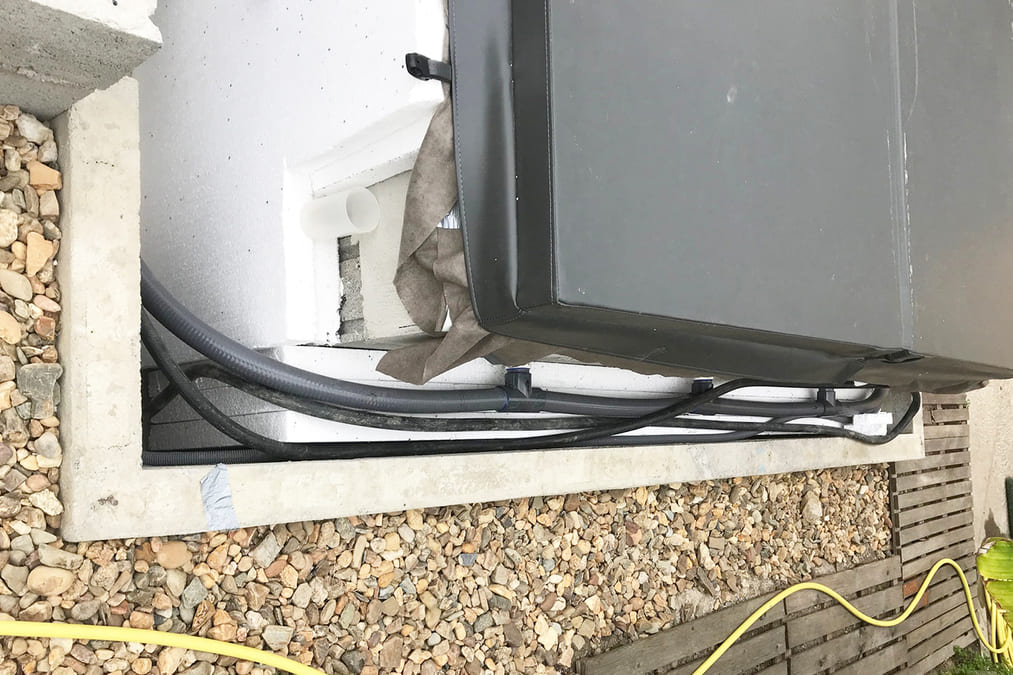
To minimize heat loss, three polystyrene insulation panels were installed around the entire perimeter of the hot tub shell.
The polystyrene provides additional thermal insulation for the concrete spa.
Three 6cm-thick panels were installed around the entire perimeter of the hot tub.
The panels must, of course, be cut where necessary to accommodate the spa plumbing.
The polystyrene provides additional thermal insulation for the concrete spa.
Three 6cm-thick panels were installed around the entire perimeter of the hot tub.
The panels must, of course, be cut where necessary to accommodate the spa plumbing.

Don't pay attention to the plumbing connections just yet. We'll cover them in the next section.
Step 6D: Connect the Hot Tub Plumbing
It's time to connect all those spa parts that were delivered to you. Refer back to the plumbing plan created during Step 1.
The setup shown in the following photo is not exactly the same as the original plan.
During the initial installation, only one suction fitting was connected to supply the massage pump. Because the 3 HP pump is powerful, the available suction flow was not sufficient to provide effective massage performance.
The second suction fitting was therefore connected as an additional branch on the massage circuit, as shown in the photo.
The setup shown in the following photo is not exactly the same as the original plan.
During the initial installation, only one suction fitting was connected to supply the massage pump. Because the 3 HP pump is powerful, the available suction flow was not sufficient to provide effective massage performance.
The second suction fitting was therefore connected as an additional branch on the massage circuit, as shown in the photo.
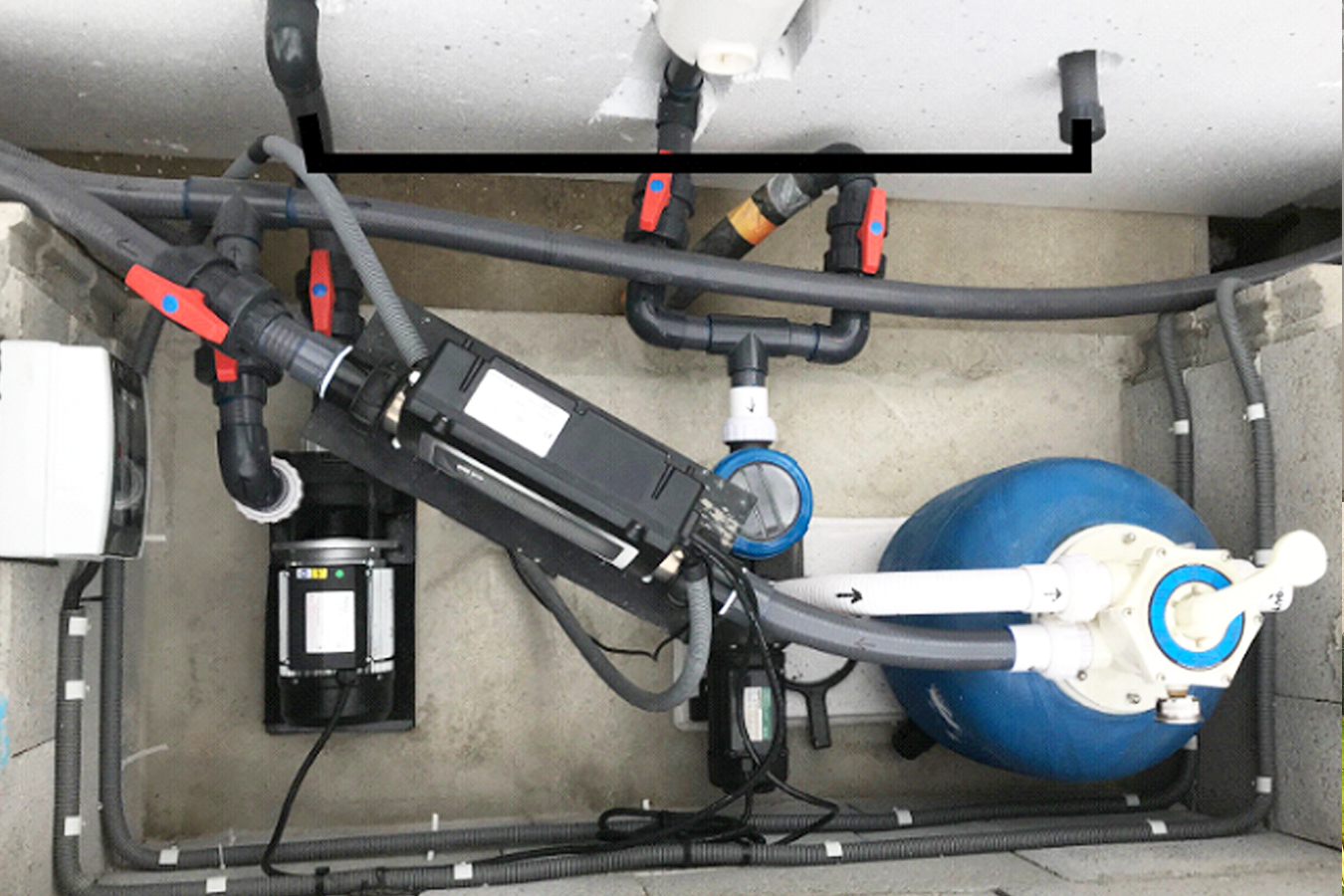
The spa control box has been positioned and secured to its support. The various PVC fittings have also been glued.
Good to Know
All spa plumbing connections must be assembled carefully using pressure-rated PVC cement.
Do not skimp on the amount of PVC cement used.
Every connection must be completely watertight. Repairing a connection after a leak has been discovered can be difficult.
Sharp-eyed readers may notice that the sand filter waste line had not yet been connected to the drain when this photo was taken.
Do not skimp on the amount of PVC cement used.
Every connection must be completely watertight. Repairing a connection after a leak has been discovered can be difficult.
Sharp-eyed readers may notice that the sand filter waste line had not yet been connected to the drain when this photo was taken.
Next, connect the different hot tub jets.
The jets are connected in series. Remember that the jet located farthest from the massage pump must be no more than 5 meters away.
The jets are connected in series. Remember that the jet located farthest from the massage pump must be no more than 5 meters away.
Use enough PVC cement to achieve a completely watertight connection. The pressure loads at these locations will be significant.
Step 6E: Connect the Spa Equipment Electrically
The hardest part is done! All that remains is to connect the different spa components to the control box.
The connections are relatively simple. The photo below shows the connection points for the different electrical devices.
The connections use AMP plugs that are very easy to install.
The connections are relatively simple. The photo below shows the connection points for the different electrical devices.
The connections use AMP plugs that are very easy to install.
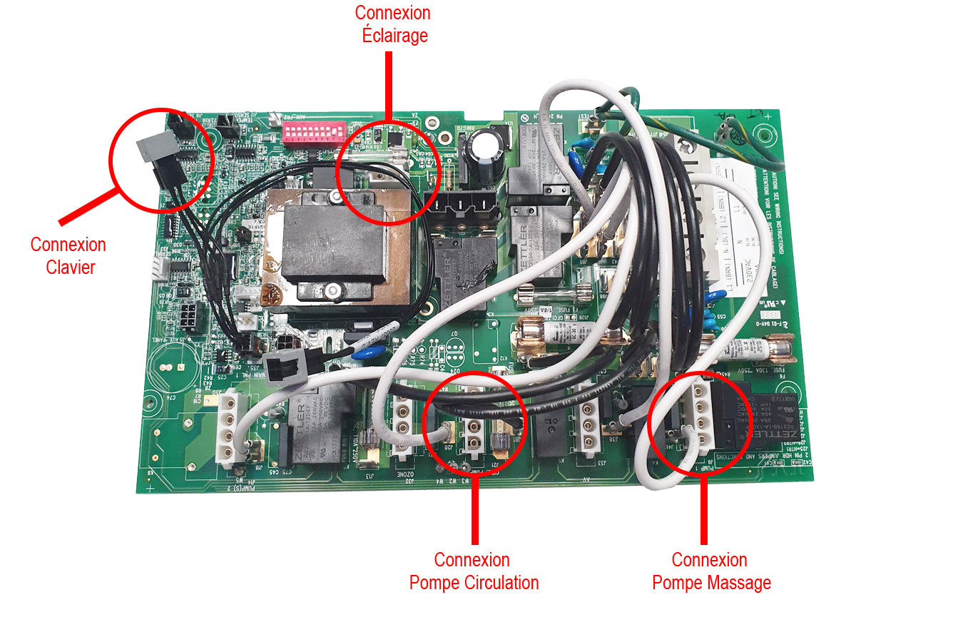
BP601 circuit board located inside the spa control box.
Good to Know
The components supplied in our concrete spa kits come pre-wired with AMP connectors. Only the lighting is not pre-wired.
Installing the connector is straightforward. The cables are crimped to the electrical pins, and the pins are then inserted into the plastic AMP connector.
Installing the connector is straightforward. The cables are crimped to the electrical pins, and the pins are then inserted into the plastic AMP connector.
Step 6F: Protect the Equipment Area and Maintain Access
The newly installed spa equipment obviously needs to be protected.
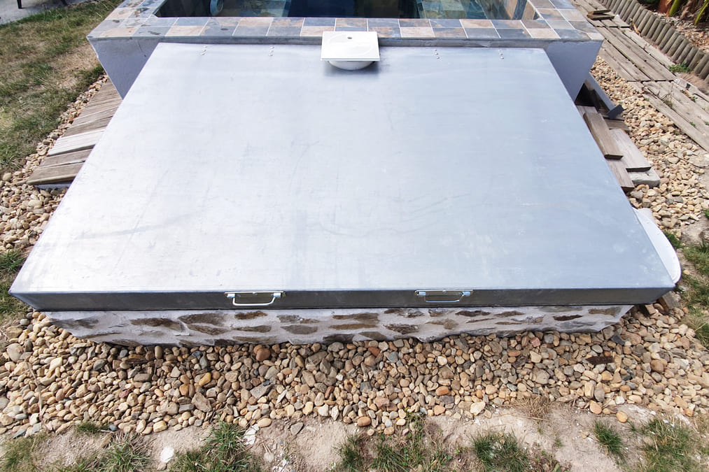
A custom stainless-steel cover was fabricated for the equipment area. We recommend taking measurements directly from your own installation.
Two hydraulic struts were also installed to make the equipment area easier to access.
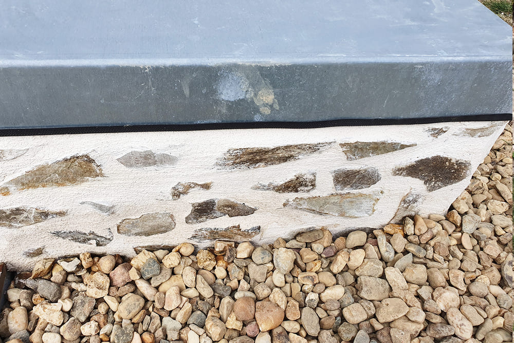
The perimeter of the equipment area was finished with exposed stone.
A custom stainless-steel cover was fabricated for the equipment area. We recommend taking measurements directly from your own installation.
Two hydraulic struts were also installed to make the equipment area easier to access.
The perimeter of the equipment area was finished with exposed stone.

Step 7: Finishing the Concrete Hot Tub
It's time to tile your concrete hot tub. Unfortunately, we weren't able to obtain photos showing the tile installation process.
We therefore cannot provide detailed information about cutting the tiles, installing them or applying the waterproof grout.
However, the photos below show the final result once the concrete spa was fully tiled.
We recommend hiring a professional tile installer.
The tile installation on the hot tub shown in this guide was completed by RENOVATIO (44).
We therefore cannot provide detailed information about cutting the tiles, installing them or applying the waterproof grout.
However, the photos below show the final result once the concrete spa was fully tiled.
We recommend hiring a professional tile installer.
The tile installation on the hot tub shown in this guide was completed by RENOVATIO (44).
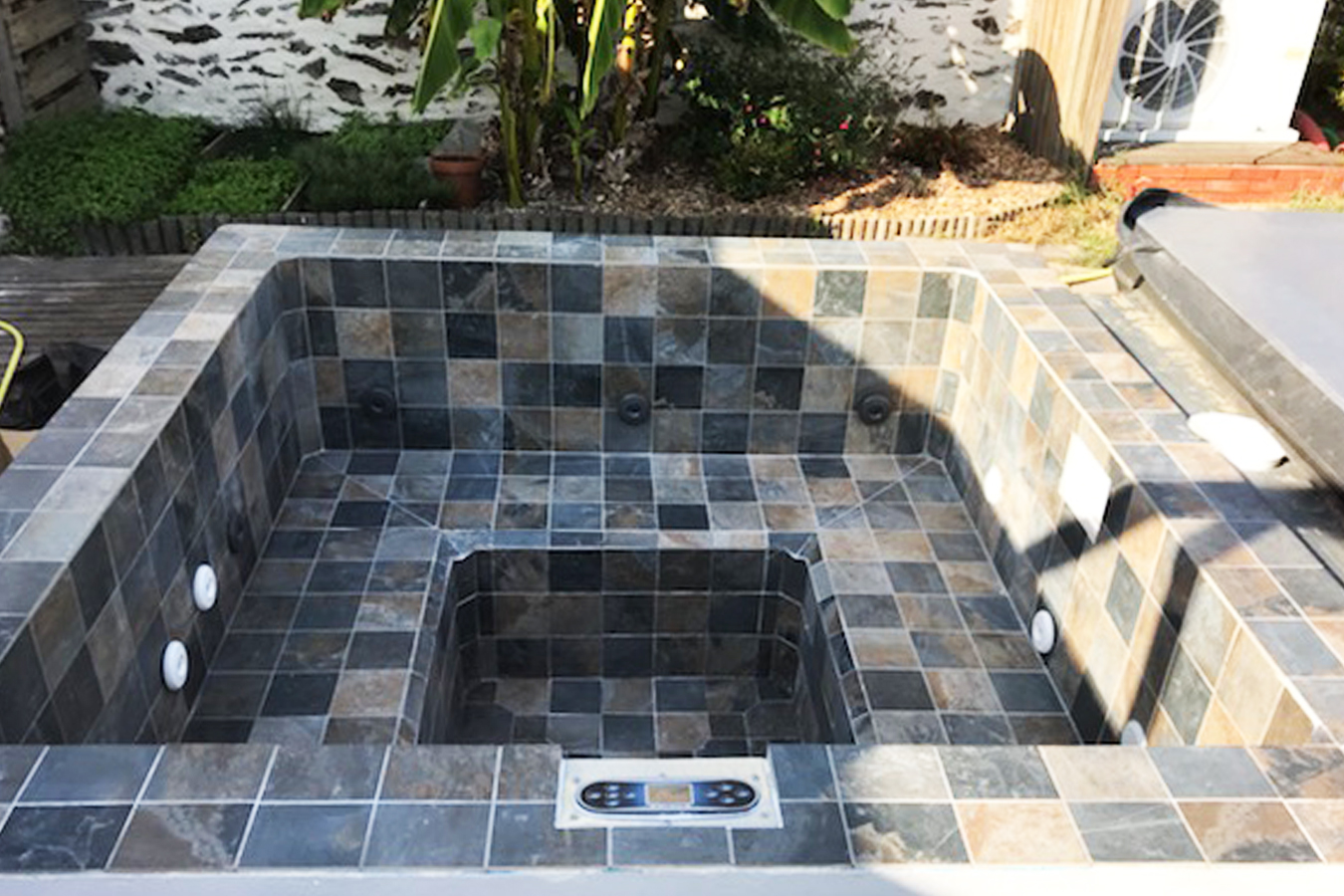
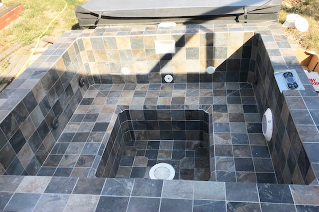
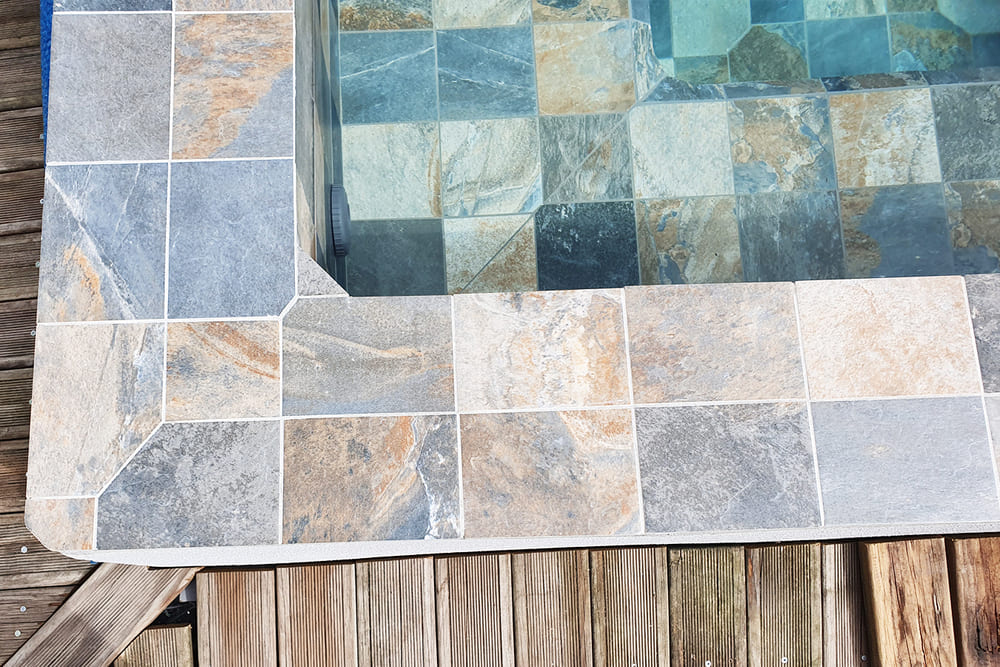
The tiles used measure 15cm x 15cm.

Close-up view of the tile cutting and installation.
Good to Know
You'll notice that finishing components were also installed.
Mr. ROBICHON selected anthracite-colored jets for the massage circuit, making them almost invisible once the hot tub is filled with water.
Other matching finishing components are also available for the spa light, skimmer and main drain.
Mr. ROBICHON selected anthracite-colored jets for the massage circuit, making them almost invisible once the hot tub is filled with water.
Other matching finishing components are also available for the spa light, skimmer and main drain.
Congratulations! You've finally reached the end of the concrete hot tub construction project. All that's left to do now is fill your spa and enjoy it!
Project Cost
Here is a detailed breakdown of the total project cost:
- Filtration kit with sand filter + BP2100 system: €1,690.00
- 6-jet massage kit: €1,048.00
- Masonry work (labor + materials): €7,000.00
- Tile work (labor + materials): €3,000.00
- Electrical work (labor + materials): €400.00
- Additional custom components (custom jet finishes, mounting supports, equipment area protection, etc.): €450
Total project cost: €13,588
Acknowledgments
We would like to thank everyone who contributed to this project. Without their help, this concrete hot tub construction guide would not have been possible.
- ROBICHON Mario, owner of the concrete hot tub featured in this guide. Mr. ROBICHON created the plans and connected the different spa components.
- BUREAU David, professional mason at Innov'Maçonnerie. Mr. BUREAU completed all of the masonry work. To contact Mr. BUREAU, feel free to visit his Facebook page: Innov'Maçonnerie
- REVEILLERE Laurent, professional renovation and tile specialist. Mr. REVEILLERE completed the tile work on the concrete spa. To contact Mr. REVEILLERE, feel free to visit his Facebook page: Renovatio
- JOLY Sylvain, author of this guide. You can contact me at: contact@boospa.com
Guide author: JOLY Sylvain
BOOSPA KIT
Ref. : A-000000-0c695
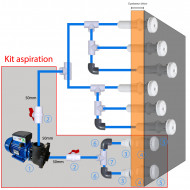
Suction Kit - Variable Speed 4-8 Jet Massage Pump
For concrete spas - To be used with a massage jet kit
Allows powering up to 8 hydro-massage jets
In stock
980,00 €
BOOSPA KIT
Ref. : A-000000-0c735
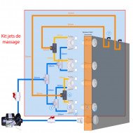
Venturi massage jets kit - 4 jets - concrete
The venturi system allows control over the jet power
For concrete spa - Max structure thickness: 15cm
Must be used with a 2 - 4 jets suction kit
In stock
399,00 €
BOOSPA KIT
Ref. : A-000000-0c772
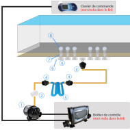
Blower Kit 6 Jets for Concrete Spa
Includes everything needed to equip a spa with an air jet system.
6 jets
Blower control via electronic command
For concrete sealing
In stock
549,00 €

BOOSPA KIT
Ref. : A-000000-0c802
12V Sequential Lighting Kit with Thick Structure
12V Power Supply - Sequential Lighting (Multicolor)
Maximum structure thickness: 25cm
Remote control included
In stock
624,00 €
BOOSPA KIT
Ref. : A-000000-0i718
Equipped with a sand filter ideal for spas with large water volume.
Includes everything needed to equip a spa with a filtration system with the electronic management system P69B133
Less popular than the BALBOA system, the Joyonway system P69B133 is nonetheless effective!
In stock
1 450,00 €
My cart (0)
No product
Product added
My account
Don’t have an account yet ?
Create my account You have an account :